Construction
The construction of this Flexor involves manufacturing a pattern that is used for the pour. This involves 3D printing the design of the Flexor’s pattern, constructing each component of the pattern to the matchplate, and sending the pattern out for pouring. The 3D prints are performed in-house here at Central Washington University and the pours will be performed at a foundry out of house. The completion of the Flexor will be finished in Central Washington University’s machine shop. The assmebly of the pattern involves the completion of the each 3D component which is them adhered to the matchplate using various adhesives. The positioning of each component has been described in the Flexor's report. A manufacturing issue that occured during construction involved the 3D printer used. There were quite a few prints that were made that were not able to be used as they were either warped or incomplete prints. To overcome this issue, there had to be time taken to fix each problem as well as time to "supervise" the prints as they were printing.
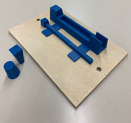
The figure found on the right illustrates the completion of five separate components to the matchplate. The Fexor shown was the first prototype to be printed. However, a re-design was in order after this part was 3D printed as shown below.
The image found on the left illustrates the assembly of more prototypes. This assembly was essentially a practice run to the actual assembly of the completed Flexor components. This allowed for any issues that arose to be address or improved before the final construction.
The image found on the right shows the 3D printer that has been used for the construction of the Flexor's part. Each part takes roughly 6-14 hours to print depending of the size of each part.


The image found to the left displays different constructed components of the Flexor's parts before they are assembled. As one will notice, the 3D prints of the Flexor itself has been split into two pieces to help with the efficiency of the prints.
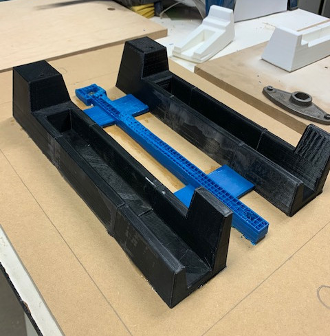
The image found to the right displays the full assembly of the Flexor's pattern. This image shows the completion of the construction before the sanding of bondo and addition of expoxy.
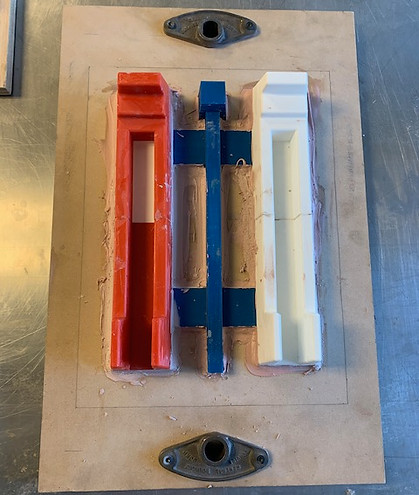

The image found to the left includes the completion of the Flexor's Pattern. The Bondo was sanded and epoxy was used over the Bondo to help incorporate a smooth fillet for the casting process.
The video to the right includes a clip of the 3D printer that was used to manufacture all of the 3D parts of the Flexor's pattern.