TestinG
Introduction
The testing that was produced for this project focused on the ability of the Flexor casting part to incorporate the clamp, micrometer, and existing strain gauge beam. This project's focus was in the dimensional aspect of the Flexor's pattern to complete a successful pour. The testing has also reflected the engineering outcome of the design requirements for the Flexor.
Method/Approach
The testing method that was conducted to the Flexor was performed once the Flexor was poured and the machining finishes were complete. Upon completion, the inclusion of the clamp, micrometer, and strain gauge beam were added to the Flexor's casting. One testing outcome for the Flexor includes the success in the incorporation of the micrometer attachment piece, the clamp attachment piece, and the pre-existing strain gauge beam. The other testing outcome conducted to the Flexor was based off shrinkage analysis to analyze how close the predicted dimensions of the Flexor were to the actual casting after being poured.
Test Procedure description
This section will be a discussion of what the procedure of testing was along with why these decisions in the testing process were made. The procedure that was used for this project will involve a pass/fail strategy. As explained before, the testing has involved analyzing the success of the attachment/performance of the clamp, micrometer, and strain gauge components. The success of this testing portion has been determined by the stability in the components and that they perform the way that they were intended to. Another testing procedure that will be conducted on the Flexor included testing for the shrinkage of the casting. This consisted of measuring the width, length, analyzing the mass, and volume to compare to the predicted values calculated in Solidworks.
Deliverables
As mentioned above there has been two “stages” of testing after the completion of the Flexor casting. A prediction prior to testing for the Flexor involves the incorporation of the strain gauge, clamp, and micrometer that will be successful and will “pass”. Another prediction that was made included the dimensional analysis of the shrinkage before and after that casting had been poured. These analyses and testings have been completed which has been explained below in the results section.
Results
Shrinkage Analysis
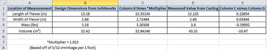
The shrinkage analysis made on the Flexor's casting illustrated values that were very close to the predicted values. The predicted values made were values calculated after multiplying the design values by the multiplier of 1.013. This multiplier value stems from the 5/32in shrinkage rate per 1 foot recommended from aluminum. The first measurement involved the length of the casting. The predicted length calculated from Solidworks was 13.35in. The actual length measured on the casting was 13.13in. This made for a difference of roughly 0.23in smaller than predicted. The next measurement involved the width. The predicted value was 2.71in. The actual width measured on the casting was 2.68in. This made for a 0.03in difference smaller than predicted. The mass of the casting was then evaluated. The predicted mass was 3.20lb. The actual mass was 3.6lb. This made for a difference of 0.40lb larger than predicted. The last analysis made involved the volume of the casting. The predicted volume was 32.84in^3. The volume was obtained with a water displacement analysis. This was calculated and recorded in an analysis below the table of values below. The actual volume of the casting was measured to be 43.31in^3. This made for a difference of 10.47in^3 larger than predicted. This could have been due to any extra flashing that was on the casting itself. Below is a table of data as well as the analysis made for the volume of the casting.

Incorporation of the Clamp, Micrometer, and Cantilever Beam
This portion of the testing for the Flexor project included the success of incorporating the clamp, micrometer, and cantilever beam attachment pieces to the Flexor's casting. There were a few challenges such as lack of access to the machine shop to make the clamp and micrometer attachment pieces. But with the help of Professor Pringle and Jim Helsius, the pieces were able to be manufactured so the clamp and micrometer were able to be attached. As described earlier, this test involved a "PASS/FAIL" criteria. The two images below illustrate the final assembly of the Flexor. As one can observe, the clamp and micrometer attachment pieces were successfully placed on the casting. Along with that, the clamp, micrometer, and cantilever beam were successfully included onto the Flexor's casting.


Overall, this project was successful despite the obsticales that occurred during the manufacturing and testing process. The shrinkage predictions were very close in value to the actual outcome of the measurements. The Flexor's casting was also able to "PASS" with the inclusion of clamp, micrometer, and cantilever beam.